SeedSigner Touch case
Print files
Slicer settings for the STL
The 3MF has all of this done. For the STL: import it, answer No when Orca asks to load the shells as one multi-part object, keep the stock presets (Ender-3 V3 SE 0.4 nozzle · Creality Generic PLA · 0.20mm Standard) and change:
| Setting | Value |
|---|---|
| Quality → Wall loops | 3 |
| Quality → Ironing type | Topmost surface (optional) |
| Support → Enable support | on |
| Support → Type / Style | tree(auto) / Organic |
| Support → Threshold angle | 30 |
| Support → On build plate only | on |
| Support → Top Z distance | 0.2 |
| Support → Top interface layers | 2 |
| Support → Interface spacing | 0.5 |
| Support → Advanced → Max bridge length | 25 |
Supports then land in three places, all reachable from outside: inside the SD-card notch and against the micro-USB slot on the base, and under the deck roof on the lid through the open USB window. The tray gets none. Every other overhang is a bridge of 20 mm or less, anchored both ends.
Optional blockers (support painting tool, hotkey L, Blocker mode): the shallow rectangle next to the USB window on the lid's underside (Ethernet pocket, 1.1 mm deep — Orca otherwise lays a pad in it that's hard to get a nail under), and the round pocket in the base's power-side wall near the USB end (AV jack — otherwise a tree grows in through the camera-tray opening in the floor to reach it). Both are painted in the 3MF already.
Assembly steps
Parts
Explode
Section cut
View
How it goes together
- Tray first. The camera tray goes into the empty base from inside and drops through the opening in the floor; its lip seats in the rebate so it sits flush with the floor top, and the cup is the 5 mm camera bump on the back.
- Camera second. It goes into the tray face-down: the lens points at the tray floor and pokes into the Ø8.5 aperture; the FFC connector on the camera's back faces up, toward where the Pi will sit. Four posts, 3.5 mm tall, hold the board up so the square sensor housing floats above the tray floor. 4× M2×5 self-tapping screws, driven from above. The ribbon leaves the camera toward the SD end.
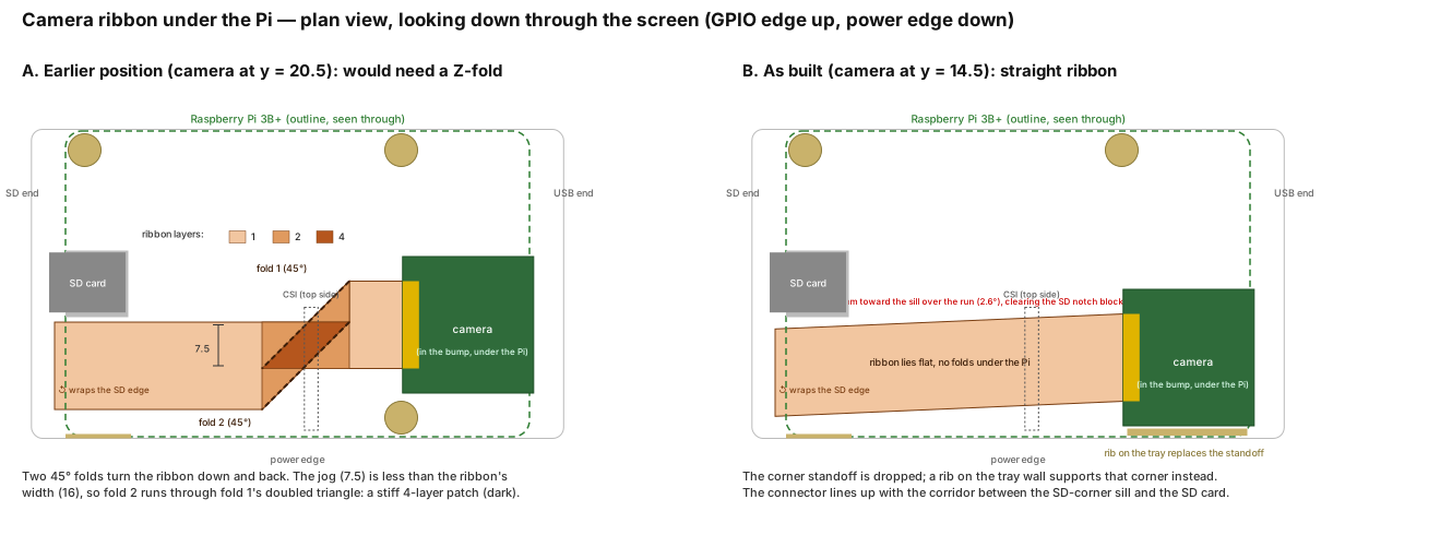
- Pi third. It sits on two 3 mm standoffs on its GPIO side, components up; on the power side the SD corner rests on a sill along the wall and the USB corner on the tray's rib (no screws there, so the ribbon has a straight run). 2× M2.5×5 screws from above; the Pi traps the tray. The ribbon runs flat under the Pi with no folds, comes out past the Pi's SD edge between the sill and the microSD card, folds up and around that edge, and plugs into the CSI connector on the Pi's top face (the vertical latch between HDMI and AV).
- Screen fourth. Press the module onto the GPIO header. Nothing else holds it — the header's friction retains it, the lid frame stops it shifting or tilting.
- Lid last. Drop it on: the deck swallows the two USB stacks and covers the Ethernet, the frame lands flush with the glass, and 4× M2.5×10 screws go in from the front (two countersunk in the face at the SD corners, two on the deck at the USB corners) into the bosses on the base's end walls.
Ribbon routing (diagram)
The ribbon leaves the camera connector heading for the SD end, runs flat under the Pi, folds around the Pi's SD edge between the sill and the SD card, and comes back along the top of the Pi into the CSI latch. A shows why the earlier camera position would have needed a Z-fold; B is the layout as built.